When I found out
that Tuff Country was coming out with a new lift kit I was very excited.
This was a lift that I could use with my Kings and adjust
them for the added weight of the winch and bumper. I also
really liked the ride of the Kings and did not want to get rid of them.
I
also had looked at the Pro-Comp 4 inch lift, but the spacer
they use on top of the factory spindle with u-bolts and a bracket ![]() to
re-enforce the spindle does not look like a good idea. I
heard horror stories about the alignment going out after every off-road
trip and such and decided it was not the way to go. The Tuff Country
kit comes with new heavy duty spindles to avoid this problem.
The
Tuff Country kit also comes with new upper ball joints installed so
you dont have to worry about getting the old ones out in one piece.
to
re-enforce the spindle does not look like a good idea. I
heard horror stories about the alignment going out after every off-road
trip and such and decided it was not the way to go. The Tuff Country
kit comes with new heavy duty spindles to avoid this problem.
The
Tuff Country kit also comes with new upper ball joints installed so
you dont have to worry about getting the old ones out in one piece.
As I go through the install of the Tuff Country 5 inch lift kit I will talk about steps in the instructions, but I am not going to type them again word for word. You can download the full instructions from the link below. I am going to try to do all of the installation that I can myself, so those of you that want to do it yourself can see what you are in for! There will also be a few links you can click on for more detailed pictures and information on some parts of the installation. If you want to see any of the pictures from the instructions in more detail and color, there is also a link below to see them in their original format.
Do you have a Tacoma Prerunner? If so, click here for some info on the Prerunner install!
Tuff Country 5 Inch Lift Instruction Manual in PDF format
Tuff Country 5 Inch Lift Instruction Manual Pictures in Color!
DMI Scrape plates for the Tuff Country lift and and others
Click HERE for all pictures of the installation.

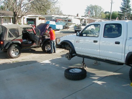
Day 1:
The kit arrived on March 16th, 2004.


Step 12 is to remove the outer tire rod from the spindle. This was not an easy task. You are going to re-use this part, so you dont want to damage it. I removed the nut completely and tapped it out with a hammer. Even though I was being careful, the treads are slightly damaged at the top. I think I can re-thread the first few and be OK.
I have since learned that if you tap on the side of the metal arount the stud it will come loose.

Steps 10-14 are removing the stock spindle from the truck. The upper ball joint is not going to be re-used, so you can get it out by taking the nut off and then pounding it out with a hammer. The new spindles come with new upper ball joints. The lower ball joint is disconnected with four bolts, so it is not a problem. The CV halfshaft just slides out of the hub center.
One trick I did find was on step number 10. You remove the cotter pin, lock cap and center nut from the stock axle where it comes through the hub. Even though the nut is not on very tight, when I went to remove it, the hub just turned. I put the key in the ignition in the on position, locked the four wheel drive button, and locked the front ARB air locker. This held everything in place so the nut could be removed.

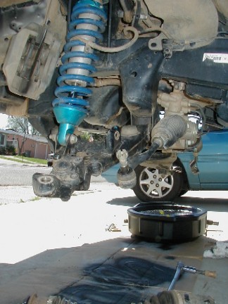
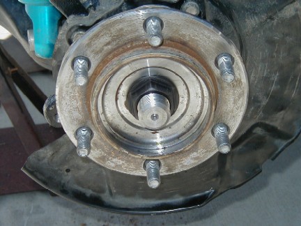
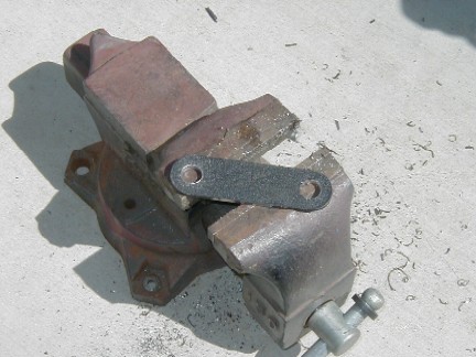
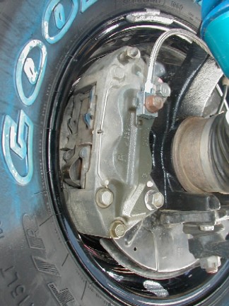
This is what it looks like with the stock spindle out.
Today I spent about 3 hours on the truck.
Day 2:
Today was the day for the outside work to be done. The front diff needed to be re-geared and the hubs needed to be pressed into the new spindles.

Day 3:
Today I wanted to make sure that all the work that I had to send out was done so we would be able to finish the lift without any more delays. My main goal for the day was to make sure that the hubs were pressed into the new spindles. The front diff was ready mid day, all I had to do was go pick it up.
I went to the machine shop where I normally go when I need this kind of work done and they were not able to press them out. They put about 15 tons of pressure on them and the hub moved a little and stopped. They were nervous about putting more pressure on them so they referred me to another shop. The second shop had about the same luck, so I headed over to Toyota.
Toyota told me that the hubs were very difficult to do. A mechanic that was at the service counter was laughing and saying something about standing behind a 3/4 inch plywood shield when the hubs were pressed out as they "explode" out. Toyota said that they send their hubs out to be pressed to a local shop called Auto Parts Unlimited. I headed down there and they said they were used to doing them and they could have them done in about an hour.
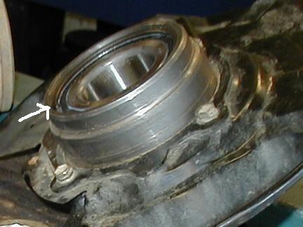
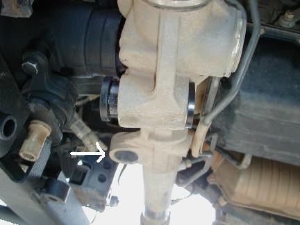
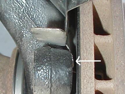
In the first picture there is a small arrow pointing at a snap ring. If you look closely, you can see one end of the snap ring by the arrow. This snap ring is behind the grease seal behind the hub. When you press the hub out, you are pushing past this snap ring, breaking the snap ring. Larry Souza, the owner of Auto Parts Unlimited who did the press work said it was closer to 20 tons of pressure used to press the hub out. (He also said that the Tundra was harder to press out than the Tacoma!)
In the second picture, you can see the hub out of the old spindle.
In the third picture you can see the hub being pressed into the new Tuff Country Spindle.
I would recommend replacing the inner & outer grease seals when you do this. You can only replace the outer when the hub is out of the spindle, and since it is not a big expense, do it while you can! The Toyota part # for my 2001 Tacoma is outer: 90312-95001, inner: 90316-69001.
I would also recommend that when you have your hubs pressed, you go to Toyota in the first place and find where they send their work to and go there!
The first two shops also slightly flattened the heads of the four small bolts that attach the splash shield to the spindle. Not a big deal, but just enough to make a box wrench not work. You need to remove these four bolts before you start the press work. A shop that does these will know this so it wont be a problem.
This was not something that I would have been able to do on the small press that I have at home.


Day 4:
The first thing we did today is remove the coilovers and put them aside to put back on later.

The lower control arms are off...
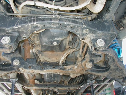
Now it was time to cut the rear crossmember out!
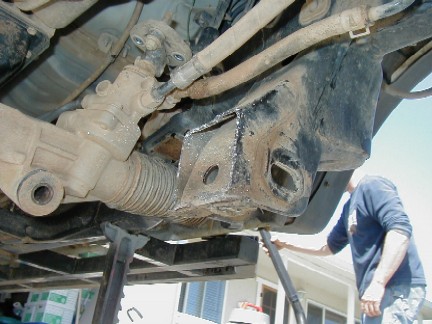


The new diff drop brackets attach to the new lower crossmember as well as the upper factory frame. As you can see here, the holes to mount the diff drop brackets to the lower frame would not quite line up. They were off less than 1/16th of an inch. After playing with it for a while, we ran a drill through it and took the square corners off.... problem solved. We should have done it in the first place. It took less than a minute to do both sides, but we wasted 30 trying to get it to line up properly.
This picture is after running the drill through.
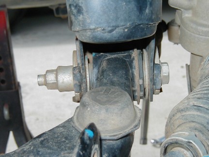
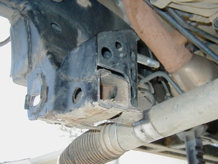
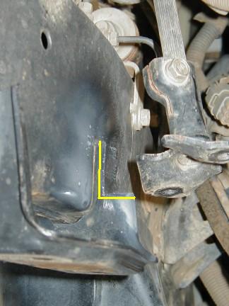
Tuff Country supplys you with new bushings for the rack. There is one new one seen here not quite all the way in, and there is another hole just behind it with the bushing out. (see arrow)
These new bushings went in tight! When you press the metal center sleve in, the rear of the bushing wanted to come out.

You also have to cut a small pocket for the pressure lines going to and from the rack. There are two layers of metal here, and we were not sure if we should cut both layers, or just one. We decided that we only needed to cut one, so when we got to mounting the rack, we found that we needed to cut both of them.... back to more cutting!! Again, it was not as easy cutting it now with stuff in the way! It would have saved quite a bit of time to have done it right the first time!
This is not an easy cut. It is lots easier to make it correctly the first time, as there is nothing in the way at this point. You dont want to cut out any more than is necessary but if you dont cut out enough, by the time you find out it will be much harder to fix!
Because of this, I have made some additional notes on this cut that you can see by clicking HERE.

The biggest problem we ran into was with the new rack bushings. The one shown by the arrow was where we had a problem... The metal sleeve that goes inside the bushing was not large enough for the factory bolt to go through. We had to remove the new bushing and put the old one back in for now. I have a complete Energy Suspension rack bushing set on order from 4 Wheel Parts, so I will put the new one in there when it comes in.
I talked to Tuff Country about the bushing sleeve. The specs were off for the final product and they are sending out a replacement.
Kits shipped in the future should not have this problem.
I would guess we spent about 6 hours working on the truck today. We could have done the same amount of work in less than 4, but we were not going at it too hard, and we did a few side things during the day, such as Kris cutting his factory exhaust off!
Day 5:
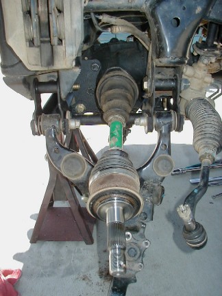
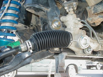
It was back to the waiting for parts game. I needed to replace the drivers side rack boot (seen in this picture) as it was ripped on the bottom. I am waiting for the new one and for some bushings that I ordered from 4 Wheel Parts so I did a little more today but not much.
I installed the halfshafts back into the front diff..

I then pressed the new inner spindle seals into the new spindles.
I would recommend replacing the inner & outer grease seals when you do the lift. You can only replace the outer when the hub is out of the spindle, and since it is not a big expense, do it while you can! The Toyota part # for my 2001 Tacoma is outer: 90312-95001, priced at $13.98 each, inner: 90361-69001, priced at $33.12 each.

When I attached the new spindles to the factory upper control arms the drivers side ball joint stud came quite a ways up, making the cotter pin useless. I talked to a friend who is a mechanic and he said that he sees this happen quite often and I should just add a few washers under the nut.
The passenger side was ok.
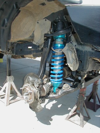
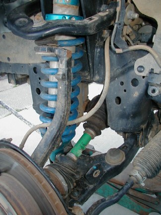
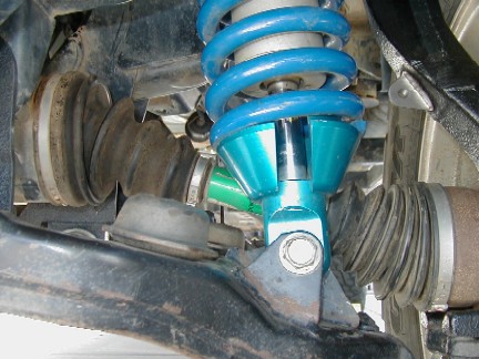
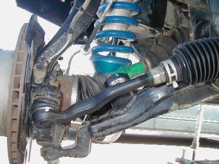
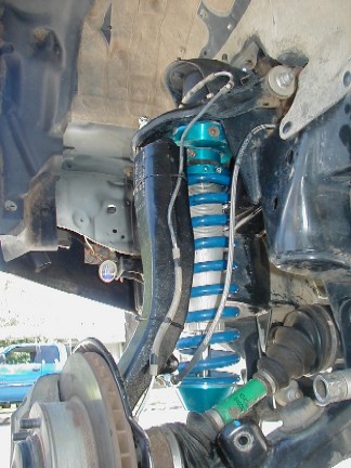
Here the King is attached at the upper point, the new spindle is attached both top and bottom and the steering is connected. I still need to do a few things, but it is getting close!
We still are working on the rack bushings, the new ones have still not arrived. The rack can be worked on when the rest if the front suspension is finished, so I will do what I can now.
Spent about an hour working today.
Day 6
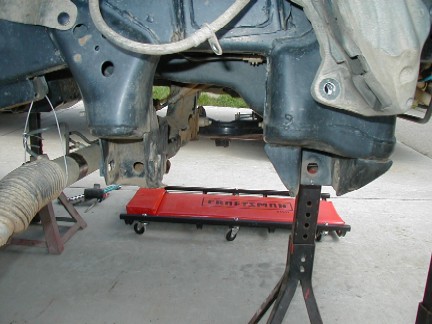
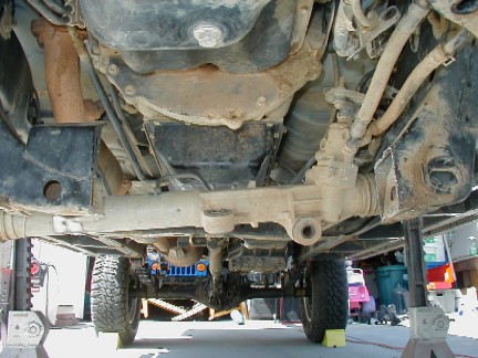
We are still playing with the rack but I wanted to get the truck off the jackstands and make progress somewhere!
I put the axle nut back on. In order to keep the axle from spinning while I tightened it I turned the key to the on position and locked the 4wd in, then locked the front air locker to keep everything still.
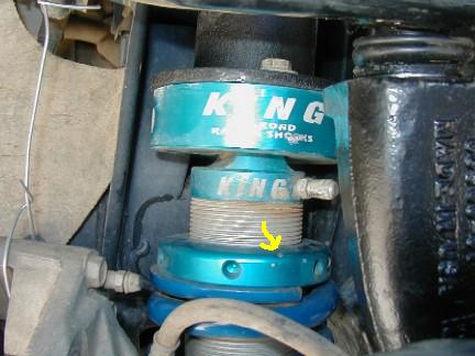
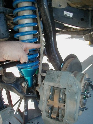
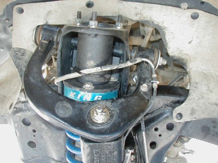
Here you can see on the spring height adjuster where it is hitting.
There is one inch of thread showing on the Kings. This is how they came set when I had them, and I am told that this is 2-2.5 inches above stock.


We also made the smaller side of the U clamp slightly larger. This should give us the room we need to make everything line up without a fight.
We have still not recieved the steering rack bushings that I ordered from 4 Wheel Parts. I called in the order on 3-16-2004 and asked them that if it would not ship on the 17th, to call me back as we were waiting for the parts and it would hold us up. They said the parts were in stock and would ship the next day, 3-17. Today, 3-23-2004 I call them and they say all the parts are not in stock and have not shipped yet. They are supposed to be shipping today and should be here before the end of the week. We will be held up on the install until they arrive :(
We spent about 1.5 hours working on the truck today.
Day 7
We took a 5 day break and went to Disneyland.... :)
We recieved 2 packages while we were gone. The first was from Tuff Country. The sleeve for the steering rack had been too small and they sent us a new one overnight UPS.
The second package was the week late 4Wheelparts Energy suspension bushings for the power steering rack. They did not end up sending the sway bar bushings. I will get them at a later time.

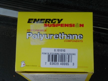
Here is the contents of the Energy Suspension kit. I have heard and read on other rack bushing installs that the sleeve with these kits has also been too small for the rack bolt to go through. I checked our kit and it was fine.
The only part we really need from this kit is the large D shaped rack bushing. All the others were provided by Tuff Country.
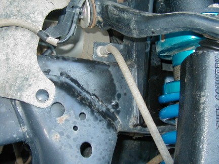
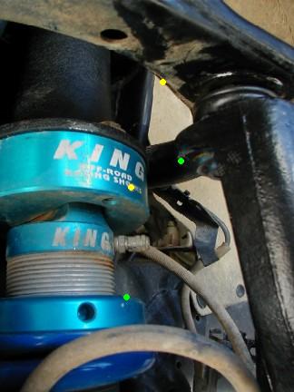
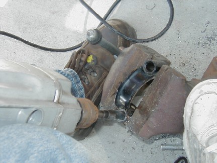
Here you can see the top of the brake line... again, there is not much room here.
You would not be able to attach the in-line mount to the spindle as there would not be enough room for flex with it attached.
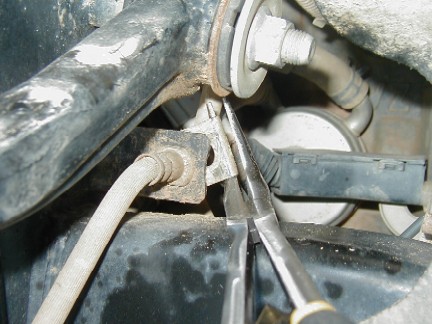
The first step in removing the factory front brake lines is to crack the top fitting, then remove the clip that holds the line to the truck mount.
You can then remove the lower banjo bolt on the caliper and remove the line.

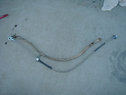
I replaced the stock lines with steel braid lines from Pro-Comp. The part number on the kit is 7213, bar code 614901180114. The kit comes with both front and the single rear.
I would recomend you replace the lines if you plan on really off-roading the truck. You may be able to free up some slack by bending the top line mounting tab.

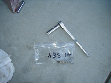
The ABS sensor line also has little slack left. If you remove all the mounting hardware except the top one, and remove the line from the clip as you see in this picture you should be OK.
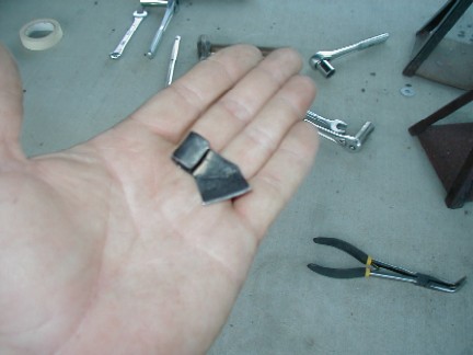
I actually cut the clip off so it will not get in the way. The long term will tell if this is enought slack and if there is any problems with the wire getting in the way.
Today I spent about 4 hours working on the truck. The majority of that time was trimming more off around the steering rack hoses. This was much more difficult now with stuff in the way. I have additional info on this step HERE.

Day 8
I started the day off right by breaking a stud on the new front coil extensions. We had to remove the passenger side King coilover so we could get to the set screw that locks the adjusting ring. For some reason the unitorque nut didnt want to come off. I took it off anyway!


I also had to replace the drivers side tie rod end as I didnt know the trick to getting them out. I do now!
The price was $ 42.72, Toyota part number 45047-39175.


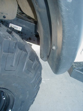
The tire is close to the plastic fender liner when you are turning. The pinch weld is behind the plastic fender liner. I will have to trim the fender liner and flatten the pinch weld in the future.
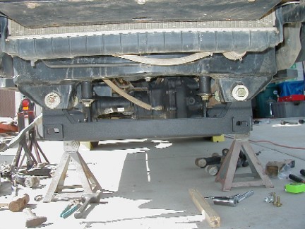
Now its time to FINALLY see the truck!!
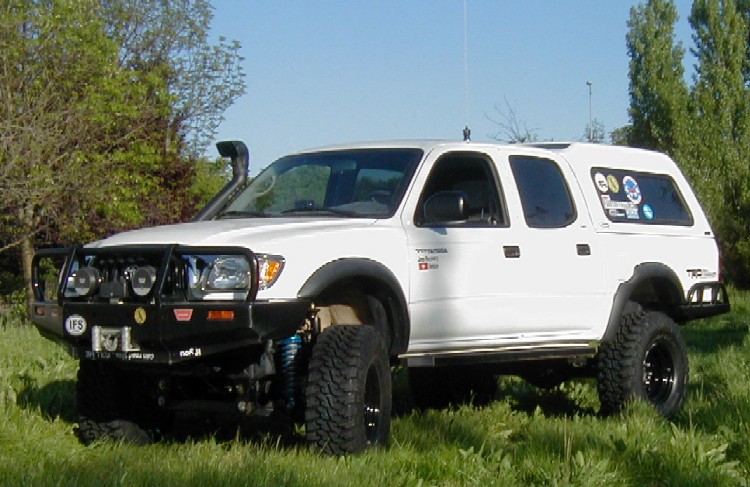
First impressions.... holy cow! I actually have to step up to get in! The ride and drive is very much the same as it was before. I would attribute this to the fact that I still have the same coilovers in the front. The rear is still bouncy as I dont have the new shock mounts made yet. It is very different feeling in that you are quite a bit higher than you were before. I am very happy with the final look.
We spent about 4 hours working on the truck today. Keep in mind that while the instructions say about how much time the lift should take, the first time is the learning experience. I think we could do another truck much faster as we know what to look out for. We also had to deal with some other things that were not covered in the lift instructions, such as adjusting the front coilovers to level the truck. Also, since we have found out some items to watch out for when you install one of these lifts, PLEASE, learn from our mistakes and it will save you time!!

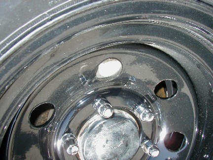
There was a rubbing noise coming from the drivers side front. It was quickly traced to the front rotor backing plate. (the splash guard)
In this picture, you can see the shiny ring where the sheet metal of the backing plate was rubbing.

You can see on the backing plate where the small rub mark is.
The backing plate was easily bent slightly back.
This closeup shows where the rubbing was. It is now taken care of.
Once the truck was back together, we took it for a spin to confirm the problem was solved.
Then it was off to Big-O Tires here in Petaluma to have the alignment checked. We talked to Randy, the store owner and let him know we were coming in on yesterday, so they are expecting us! We told them that we had installed the lift so they should be prepared for it to be WAY out!

First Alignment right after lift install:
When they were finished with the truck, they said that they were very suprised as the alignment was not that bad. The tech said that they see vehicles that are lifted come in all the time for alignments and they can be WAY out of alignment. Considering the front was all taken off and spread around the driveway it was pretty close!
Here is a copy of the before and after alignment specs.
Big-O has a 6 month alignment warranty. After things get settled in I will take it back and we can see how much if any the alignment has changed.
The rear springs will settle in and the front coilovers may need to be adjusted more when that happens. That will most likely affect the alignment some.

Second Alignment, 3 months later:
It has been just over 3 months since we installed the lift and we were able to take it out and wheel it a few times. I wanted to see if the alignment would stay put, since this is an indicator if the parts are moving around.
You can compare the "Current Measurements" from the last alignment with the "Before Measurements" on this one and see the difference.
Since the last alignment, we have added 75+ pounds to the front end. The rear Alcan leaf springs have setteled in some, in effect lowering the rear of the truck slightly.
We will have another alignment check done at the 6 month mark. This will let us take it on a few more runs, including TTORA Takeover and Run-A-Muck, and maybe even our upcoming Rubicon run.
So far, the lift has stayed put and the alignment has not gone out.
I have also not had any problems with anything else. I am still very happy with the lift.

Here is the third alignment. This is after the TTORA Takeover run and also Run-A-Muck. Things still seem to be hanging in there. They had some problems getting everything in the green, but overall gave it a thumbs up.
Right after this alignment was done, I replaced the factory upper control arms with AllPro Off-Road's uniball uppers. This actaully helped the alignment.
